

✔ worldwide delivery
✔ Refund for lost or damaged packages

✔ We offer a variety of secure payment methods, including debit/credit cards, PayPal, and bank transfers.
✔ Every transaction is protected
✔ 100% Authentic, Official Warranty
✔ Returns within 15 days – quality issues only
-33.svg?w=256&h=256)
✔ 24-hour response
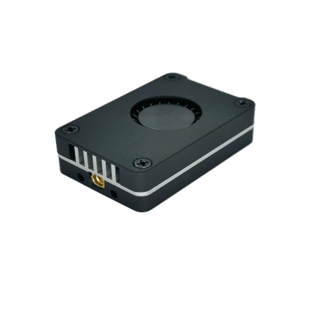
About this product
Feature
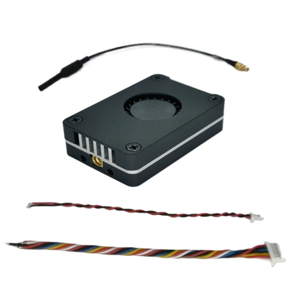
Package Included:
Transmitter wiring diagram:

Transmitter operation adjustment section:
1. Frequency table

Note: 400mW, 800mW, 2500mW, power levels must be in good contact with the matching antenna. Otherwise, the power cannot be transmitted and the power amplifier will be burned out.
Note: When using the extended frequency group, please choose an antenna that supports 4.9G (Group 7, Group 8) and 6G (Group 9) frequency bands, or choose a full-band antenna to achieve
Optimum transmitting distance (it is recommended to choose the antenna recommended by the manufacturer). The copper tube antenna shipped standard does not support use on the extended frequency group. The high-power transmitting antenna does not
Matching will burn the mod.
2. Use one button to adjust the power. Short press to change the power and cycle between the four gears: PIT, 25mW, 400mW, 800mW, and 2500mW. green light for work
The rate indicator light, the status is as shown in the figure below, 25mW flashes once, 2500mW flashes 4 times in a row. Press and hold for 3 seconds to enter PIT mode, the green light will stay on. Red indicator light Steady on Flashing 1 time Flashing 2 times Flashing 3 times Flashing 4 times
(This image transmission has a temperature protection function. When the temperature of the image transmission is higher than 100℃, the transmission power of this image transmission will be reduced by one level. If the temperature is still high
At 100°C, continue to reduce one level until the lowest power level (25mW); when the temperature drops to 95°C, the transmit power will return to the original level.
Set power level. )
3. Use one button to adjust the frequency group/channel. Short press to change the channel, and long press for 3 seconds to change the frequency group, as shown in the figure below.
48 Channel group control Press and hold the Band/CH key for 3 seconds to switch frequency groups
Channel Group BAND A BAND B BAND E BAND F RaceBand BAND L
Blue indicator light flashes 1 time flashes 2 times flashes 3 times flashes 4 times flashes 5 times flashes 6 times
Channel control: Short press the Band/CH key to switch channels
Channel CH1 CH2 CH3 CH4 CH5 CH6 CH7 CH8
Green indicator light flashes 1 time flashes 2 times flashes 3 times flashes 4 times flashes 5 times flashes 6 times flashes 7 times flashes 8 times
4. Press and hold the power button (Power) and FM button (Band/CH) at the same time for more than 5 seconds to switch between the normal frequency group (48CH) and the extended frequency group (24CH).
After switching, the power must be cut off and then powered on again to take effect.
Switch the regular frequency group (48CH) to the extended frequency group (24CH), and the three indicators will flash once at the same time;
Switch the extended frequency group (24CH) to the regular frequency group (48CH), and the three indicators will flash twice at the same time;
Note: The regular frequency group and the extended frequency group can only be switched by pressing the button and not by protocol. After switching, the frequency point can be switched through the IRC protocol.
5. Remote control operation OSD parameter adjustment instructions (serial port control parameter adjustment) (TRAMP protocol):
(The image transmission power levels of the flight control OSD are 25,400, 800, and 2500, corresponding to the local transmit power: PIT 25mW, 400mW, 800mW,
2500mW;)

DIY Notes:
加载中


